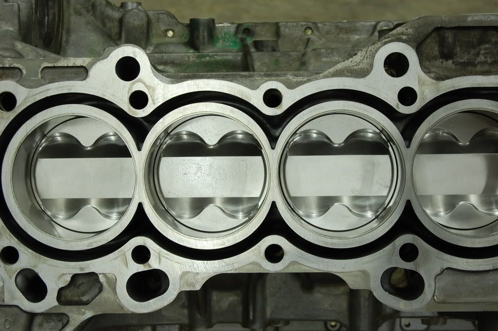
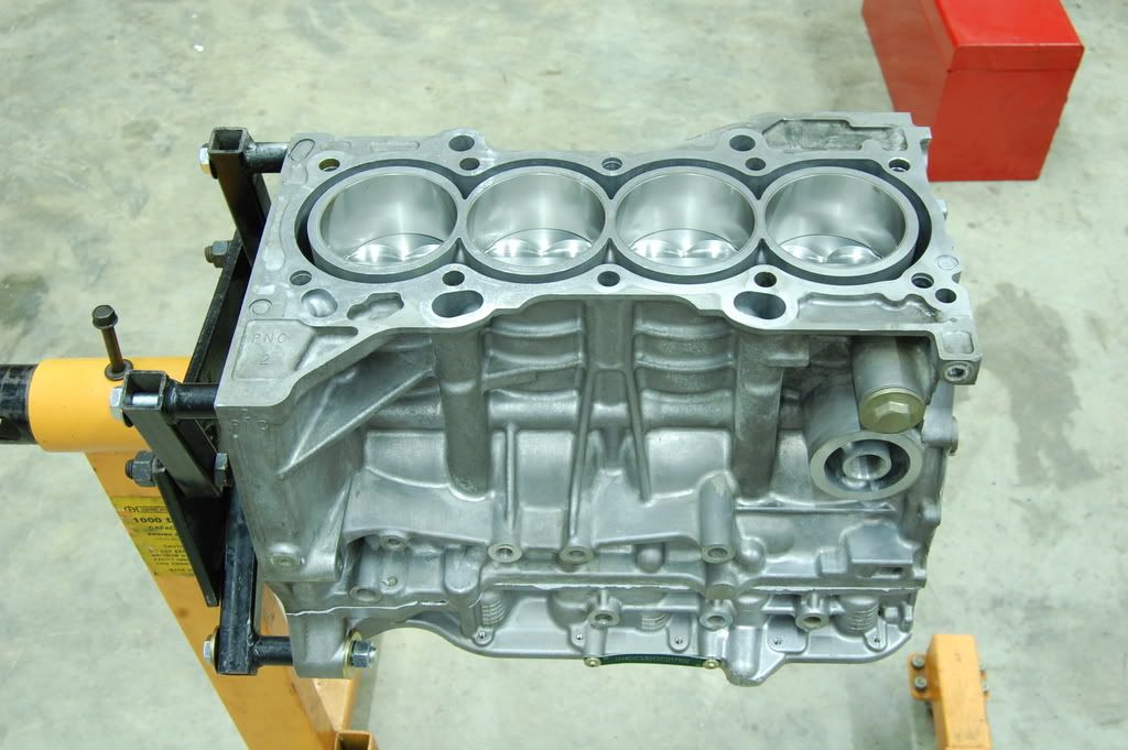
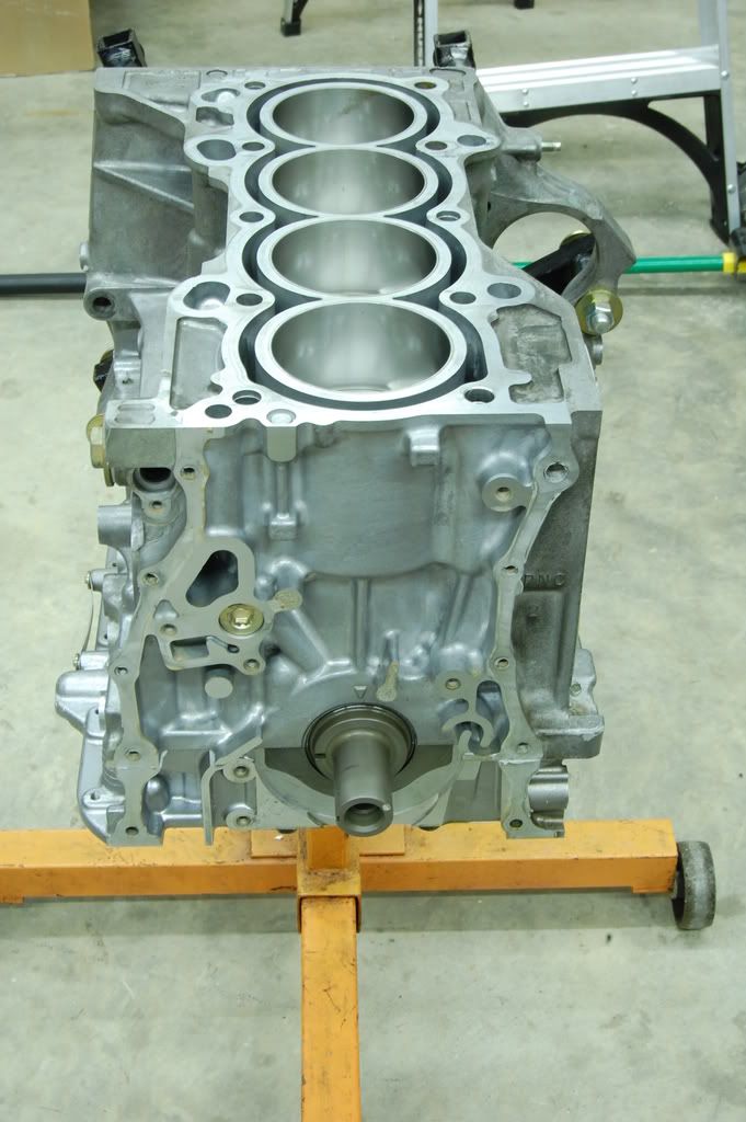
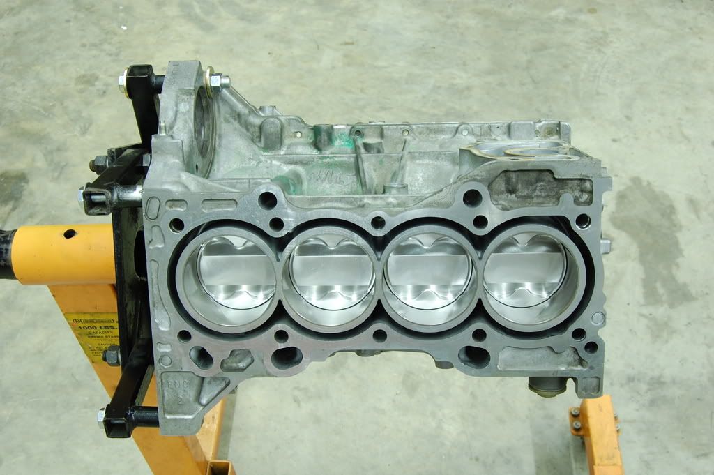
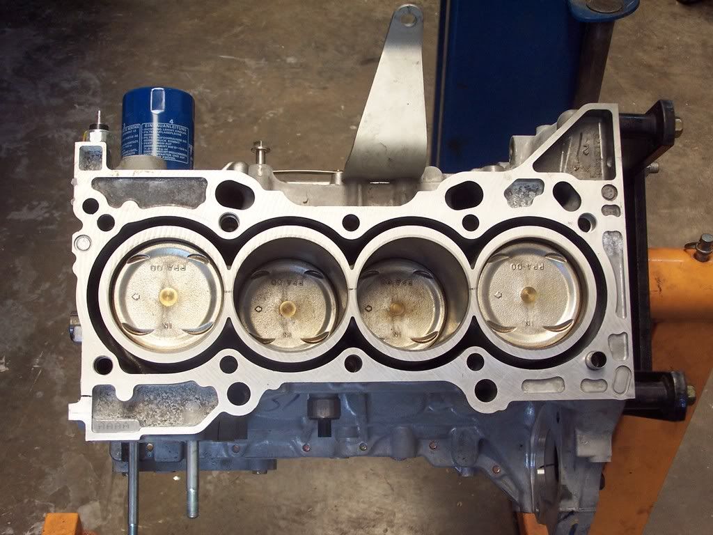
It is well known that racing engines require stronger components in order to withstand the increased forces. Race engines use components such as titanium valve springs, forged rods, large diameter head bolts, and ductile iron sleeves to name a few. Many of these components have been developed through the years with the simple trial and error method. If the engine blows, find out why, and strengthen the component that broke. This technical brief will show you how an engine sleeve is designed and tested utilizing engine simulation and finite element analysis.
When the spark plug of an internal combustion engine fires it ignites fuel that starts an exothermic chemical reaction. This reaction creates high temperature gases that greatly expand. These expanding gases cause a large increase in pressure in the cylinder. This pressure forces the piston downward. This pressure is also putting a tensile stress into the engine sleeve. In other words the pressure in cylinder is trying to blow the cylinder apart.
This particular technical brief will be the structural analysis of a turbocharged Honda K24 engine with the ERL SUPERDECK Ι system and Darton sleeves. A turbocharger forces air pressure or “boost” into an engine. Boost without exception causes an increase in combustion pressure. Both mean effective pressure and maximum pressure are increased. Therefore, the first step in analyzing this engine is to find the maximum combustion pressure that a turbocharged K24 sees while running down the track.
In order to find the maximum combustion pressure theoretically, a commercial off the shelve program was used. This program allows the user to define the specifications for the engine block, head, intake system, exhaust, valve train and of course the turbocharger. In order to test the absolute extreme conditions in racing engines at this time the turbocharger boost was set to 45 psi at 10000 RPM. This particular engine had an output of well over 1200 horsepower and approximately 1000 lb ft of torque. Below is a graph of the cylinder pressure vs. crank angle at 7000 RPM. This RPM point is where this engine is making maximum torque. In a correctly tuned engine the maximum torque point always corresponds to the maximum cylinder pressure. As you can see the maximum combustion pressure is approximately 6000 psi at 16 degrees past TDC.
The next step of the analysis is to apply this cylinder pressure to the K24 engine sleeve in order to determine the stress in the sleeve. Once the stress has been determined, it will be compared to the allowable stress of ductile iron. A modeling/finite element analysis program will be used to do this. Finite element analysis (FEA) is a mathematical method used by many engineers to analyze parts with complex shapes by breaking the parts into small elements that make up an area or volume defined by a set of points called nodes. The nodes and elements together make up the mesh which contains the material and structural properties of the part being analyzed. A load or displacement is applied to a surface or point. Using matrices the program propagates the displacement throughout the part from one element to the next through overlapping nodes. This displacement is used to calculate the stress in the part in every element. Below is the K24 sleeve with the applied mesh, loads, and constraints.
The constraints are a very important part of the sleeve analysis. The constraints need to replicate the reality of the engine as closely as possible. In this instance there are three main constraints
1. The sleeve is not allowed to move up due to head bolts locking the head down the block.
2. The sleeve is not allowed to move down due to the bottom of the T head being constrained by the
engine block.
3. The sleeve’s T head is not allowed to move out radially because the side of the sleeve is
constrained by the ERL SUPERDECK I system.
These constraints are replicated by the finite element model by applying degrees of freedom constraints to the applicable surfaces. In this analysis there is only one load, combustion pressure. However, this load is not uniform on the internal surface. The above graph shows how the combustion pressure varies vs. crank angle. This means that as the piston is pressed downward in the cylinder the pressure decreases. Using an equation that varies the load as a function ofthe distance down the cylinder, the correct combustion pressure was applied in the cylinder.
The next step in the analysis is to interpret the results. The finite element program used allows the user to display directional stress, max principal stress, Von Mises stress, displacement, and the strain in the part. These values along with known material data will determine whether the sleeve will fail or survive. The Von Mises stress uses an equation to combine stress in all three dimensions(x,y,z) into one number. This number is then compared to the tensile strength of the material when loaded in one dimension. If the Von Mises stress is lower than the tensile strength of the material then, the material will not yield when loaded. It is critical when designing an engine sleeve that will be loaded thousands of times a second to keep the sleeve from yielding. If the sleeve does yield it will eventually crack and fail. In this analysis the two main values that were looked at were the Von Mises stress and the maximum displacement.
The two pictures located in the downloadable version show a plot of both the Von Mises Stress and the max displacement. The displacement plot shows a 110X scale deformed shape. This helps to show visually the way in which the sleeve is deforming even though the max displacement is less than .003″. As shown the sleeve is not deforming at the T head. The body of sleeve on the other hand is deforming or bubbling out. This result matches reality. As the previous section stated the T head is fully constrained in the radial direction whereas the body of the sleeve is not constrained. As you can see the deformation decreases as you look down the sleeve. This is due to the fact that the combustion pressure is decreasing as the piston moves down the sleeve.
The Von Mises plot on the left shows that the majority of the sleeve is subject to stresses ranging from 7,500 pounds per square inch (psi) to 40,000 psi. The area directly below the T head of the sleeve is shown in the small picture to have stresses ranging from 50,000 psi to 75,000 psi. This is caused by the abrupt decrease in thickness of the sleeve as well as the change of constraints. With the T head fixed and the body unconstrained a moment or torque is applied about the T head. The sleeve is behaving like a cantilevered beam. If the sleeves were made of common cast iron then, this would be a critical issue. However, all ERL sleeves are made of Darton’s Ductile Iron. The known yield strength of Darton’s ductile iron sleeve is approximately 110,000 psi. This sleeve will not yield.
In Conclusion:
1. With the use of engine simulation and finite element analysis an engine sleeve can be designed
and tested without breaking any components.
2. A stock K24 Honda engine has a combustion pressure of approximately 1200 psi, the above
turbocharged K24 engine has a combustion pressure of approximately 6000 psi. This is the reason
why drag race teams use Darton sleeves and ERL SUPERDECK I and II
3. It is very important to constrain the engine sleeve using ERL SUPERDECK I and II Systems. These
systems allow the T head to distribute the stress into the engine block and ensure a stable sleeve
head which aids in head gasket sealing.
4. The K24 sleeve shown above had a max Von Mises stress of 75,000 psi. With a typical yield stress
of less than 40,000 psi for cast iron versus a typical yield stress of 110,000 psi for Darton’s Ductile
Iron. It is clear why ductile iron sleeves are necessary in race engines.
To purchase engine parts click here!
For any engine building inquiries please email here!
